


The SQM is made to mate kinematically with a radiometer, aka Device Under Test (DUT). The problem is the YES SQM was primarily for the Satlantic OCR, OCI style radiometers, so we can either make new mounting flanges or adapt our heads to the existing flange, which has a 4.125” ID. Mark and I decided to adapt to the existing flange.
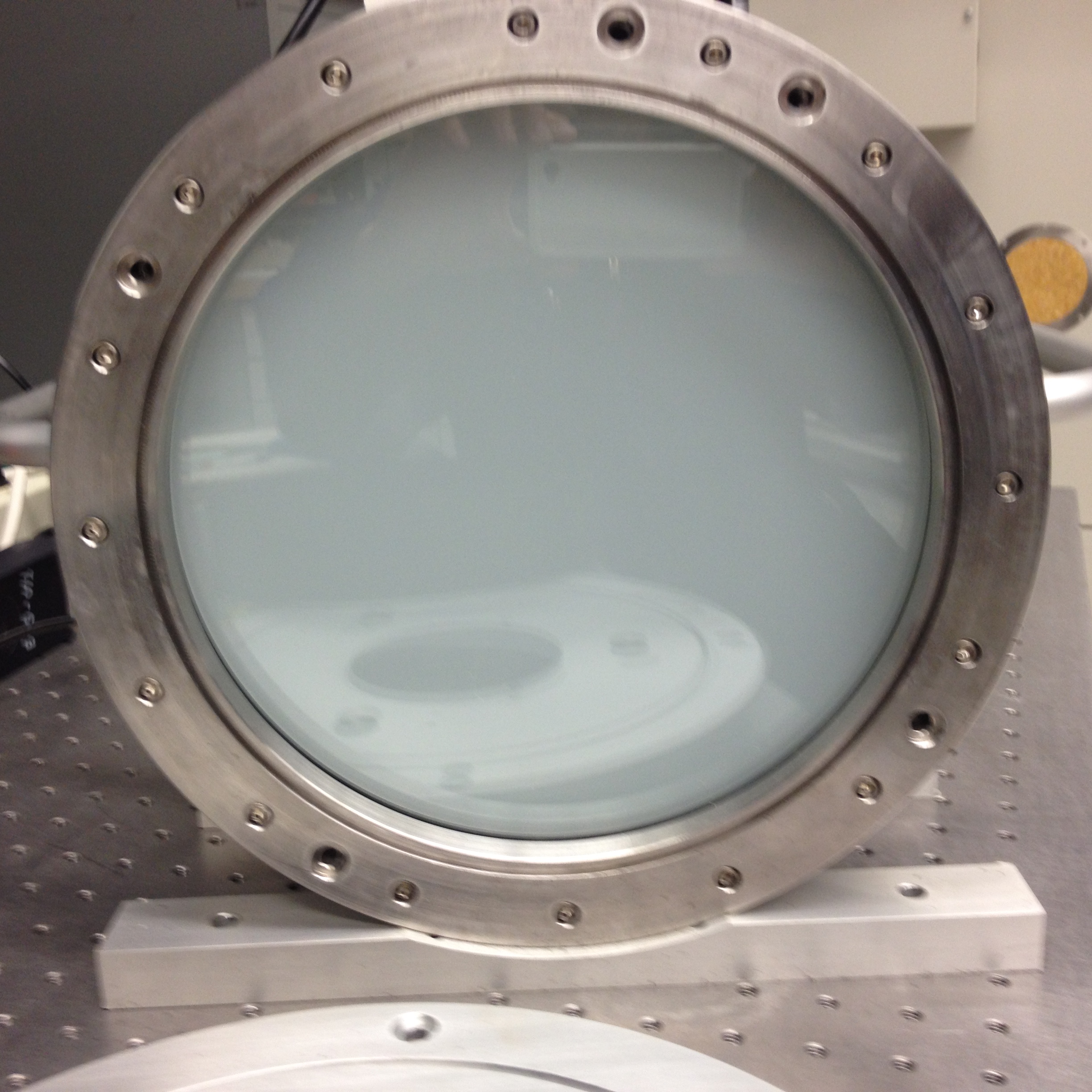
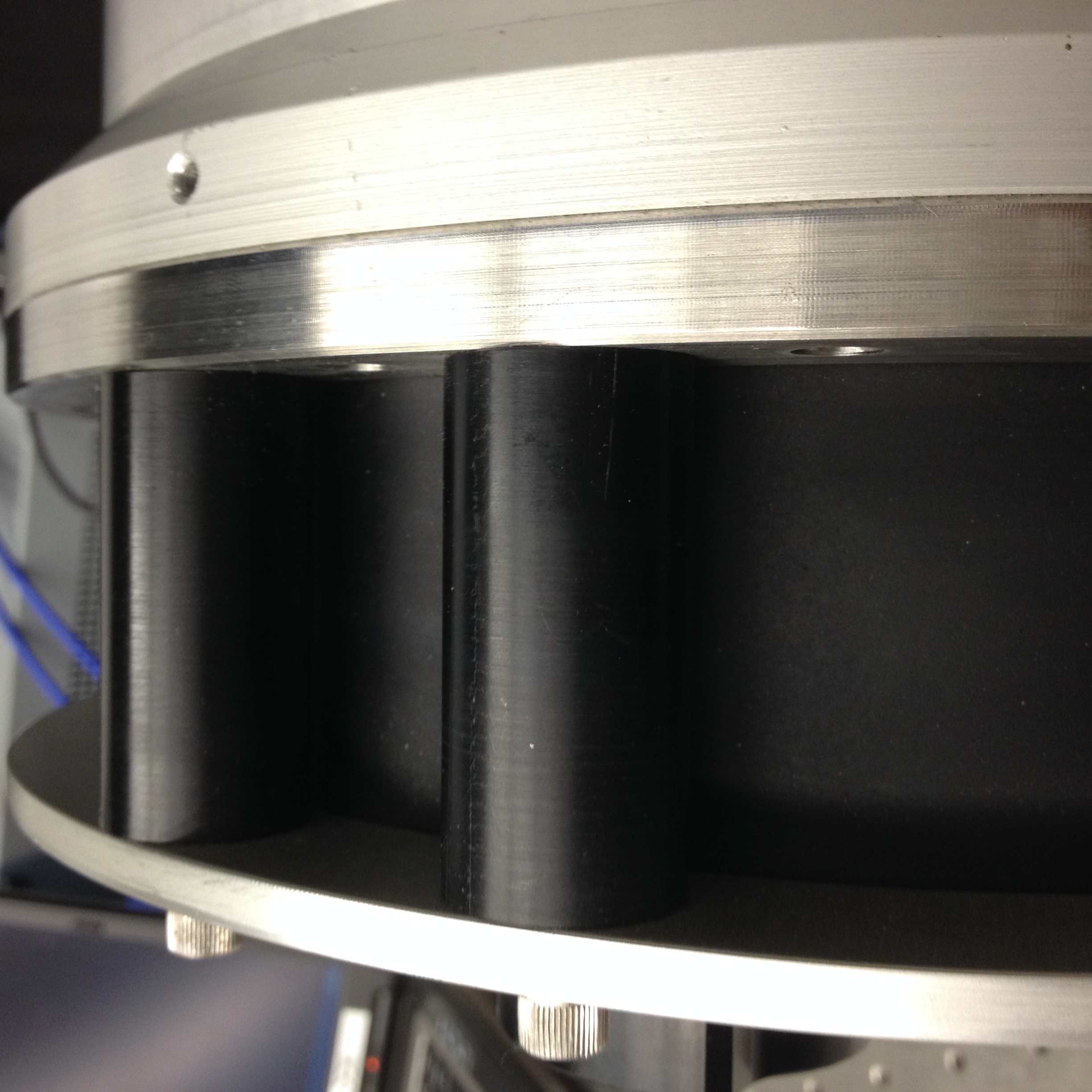
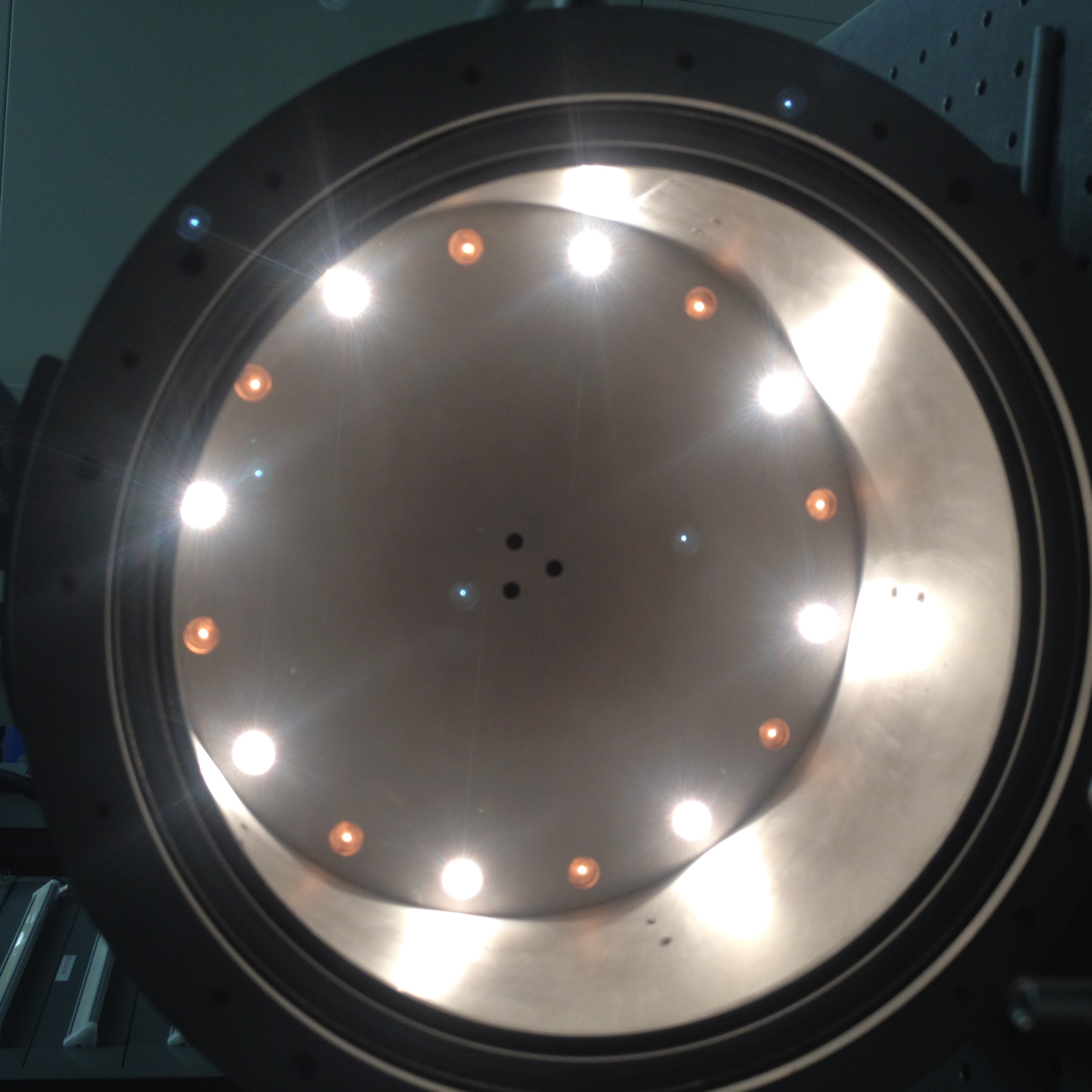
The YES SQM (see the manual under “Documentation”) has two lamp rings on the outer diameter of the back wall of a cylindrical chamber. See Photo SQM_no_front_lamps_on.jpg attached. The walls are bead blasted aluminum. The front is a piece of acrylic diffuser, 9.375” +/-0.005” diameter by 0.114” thick (actual). It is protected by a glass window, 9.914”+/-0.005” diameter, 0.370” thick (best vendor effort). O-rings and a large plastic washer seal and protect these parts. The window/diffuser are held in place with the SQM front flange. See IMG_1420.jpg attached for how this looks assembled. The SQM adaptor plate is spaced away from the flange using a light tight ring (IMG_1413.jpg), which is held in place by the SQM mounting flange. Looking into the assembled SQM (IMG_1411.jpg) you can see the DUT is held in place by the black locking rings. In the attached PDF file, Figure A is the adaptor plate, Figure B is the light tight ring, and Figure C is the spacer (there are five in total) – see the attached file “SQM Front Flange Assembly.pdf”.
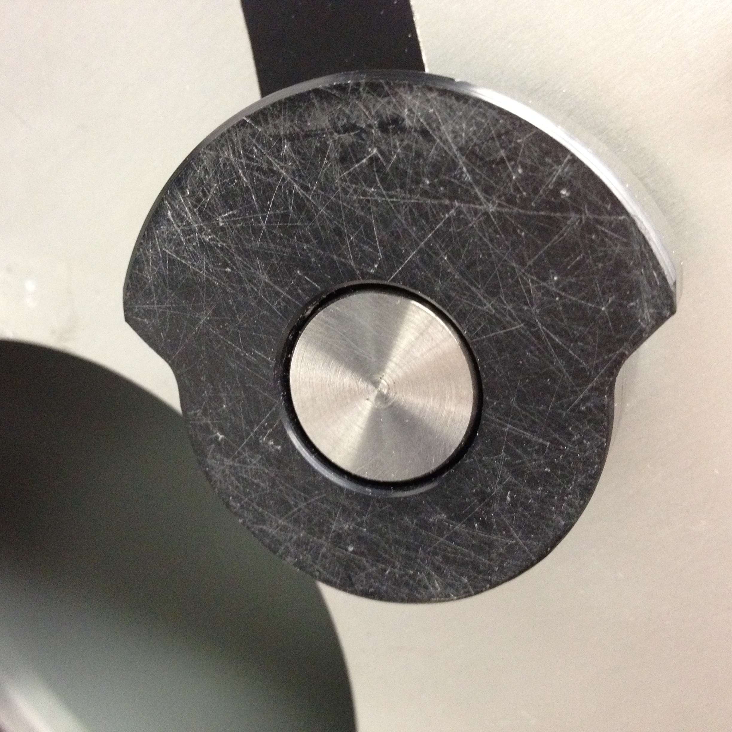
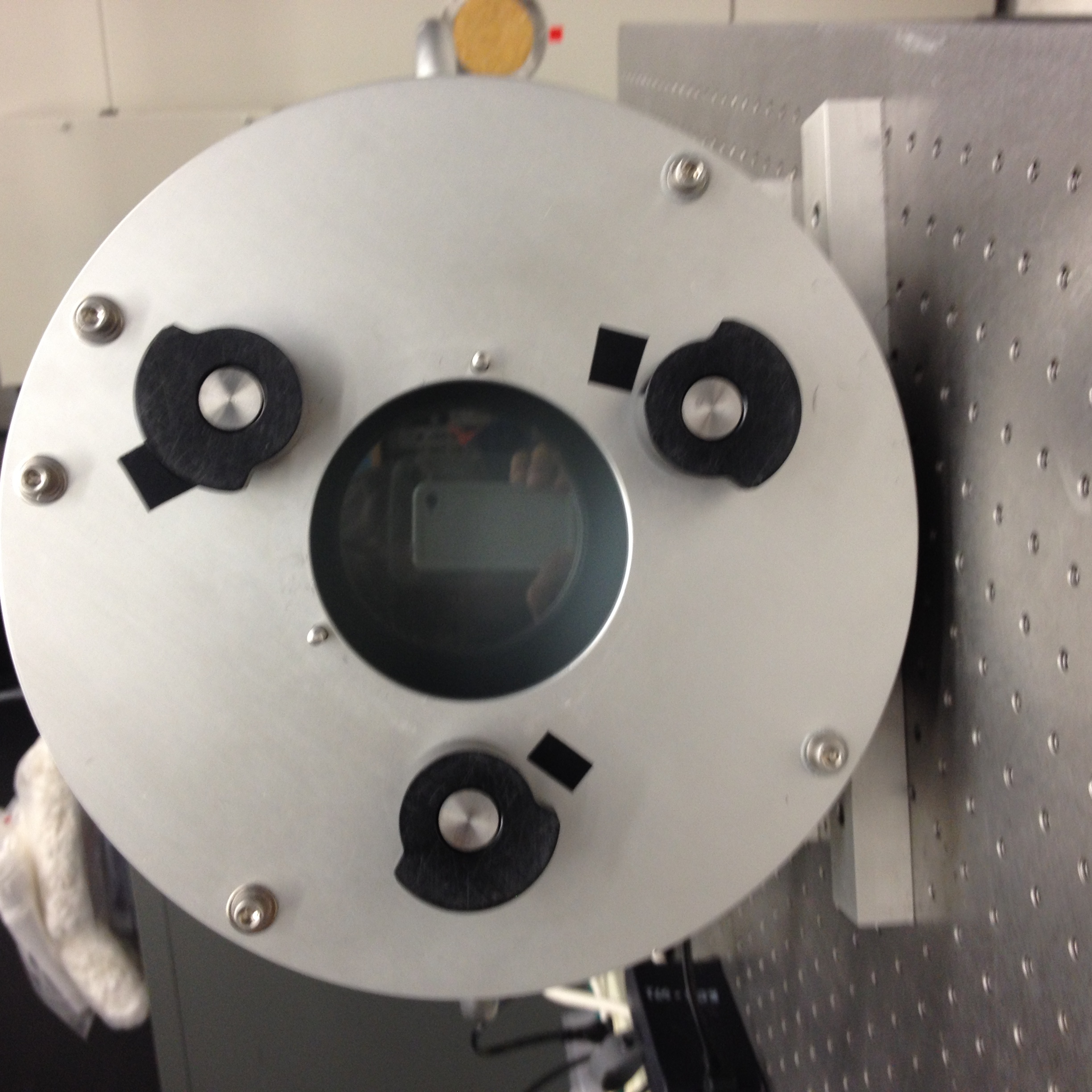
The YES SQM adaptor plate holds the DUT in place with the black locking rings (IMG_1405.jpg). To fit into the existing adaptor plate and be locked under these rings, a part needs to be 4” in OD, protrude not more than 1.5” past the plate into the light tight chamber, and have a lip/flange that is 4.95” OD by 0.5” thick. It should also have two holes for mounting to the mating pins on the SQM adaptor plate (I’ll need the shops to measure the pin locations for us). I envision the CAS radiance fiber assembly and the MOBY heads to fit into a fixture of these overall dimensions. They need to be designed and made for the CAS’. For MOBY, Mark envisions a detachable part that is kinematic on both sides – so it goes on the MOBY head at the same azimuth and location back from the window, and ditto for the side that mates to the SQM.
|
| SQM_no_front_lamps_on.jpg |
|
| The window/diffuser are held in place with the SQM front flange. |
|
| The SQM adaptor plate is spaced away from the flange using a light tight ring |
|
| Looking into the assembled SQM you can see the DUT is held in place by the black locking rings |
|
| The YES SQM adaptor plate holds the DUT in place with the black locking rings |