REVISION DATE: 28-Jul-2015 11:37:03
Fiber Optic Splitter Test:
Mikes email: Right now we are trying to check the spec sheet that came with this first splitter i.e doc = FO_Splitter_01.jpg, where they state the power split between the two legs should be 56.86 % and 43.14 %. Hence, BS1 FO#7 viewed the incandescent source in the sphere, then the single-end of the splitter was attached to the source and the two legs were viewed via BS1 FO#7 individually. I think a portion of the FO#7 signal from step#1 @ sphere will be lost at the FO-to-FO connection when FO#7 connects to one or the other of the two split fiber ends.
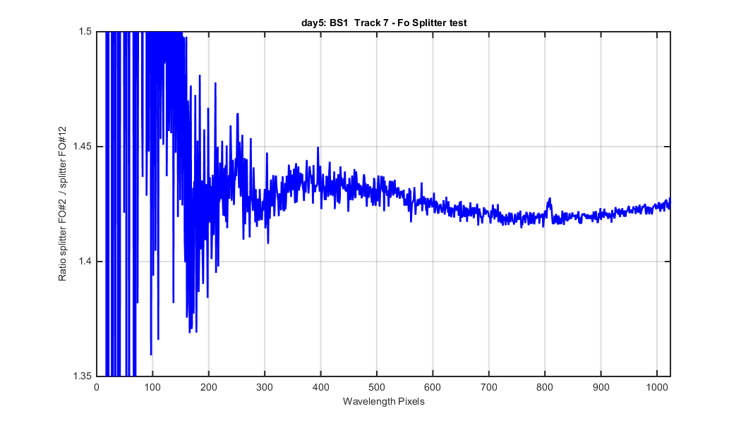
This is the day 5 FO splitter test data Mike took. I normalized the data by the PD monitor values Mike included in the log sheets. All the data have been dark subracted, divided by integration time and is a track mean, hence the (ADU/pix/sec) units. The idea is to confirm that the data Mike took conforms to the 56.86 % and 43.14 % power split between the two legs of the splitter. FO#1 is the "WEAKER" fiber and FO#2 is the other fiber.
Figure 1
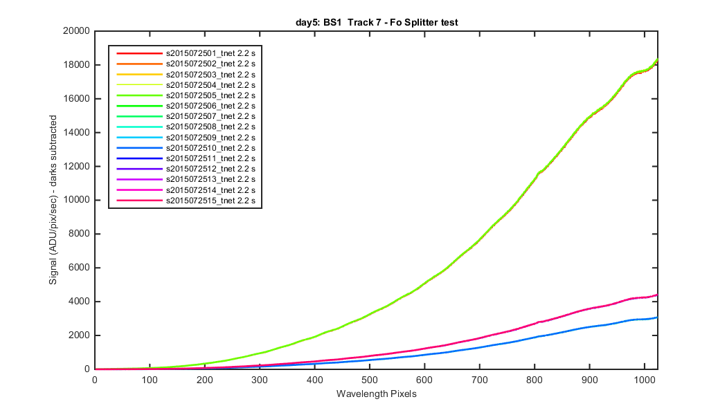
Figure 2
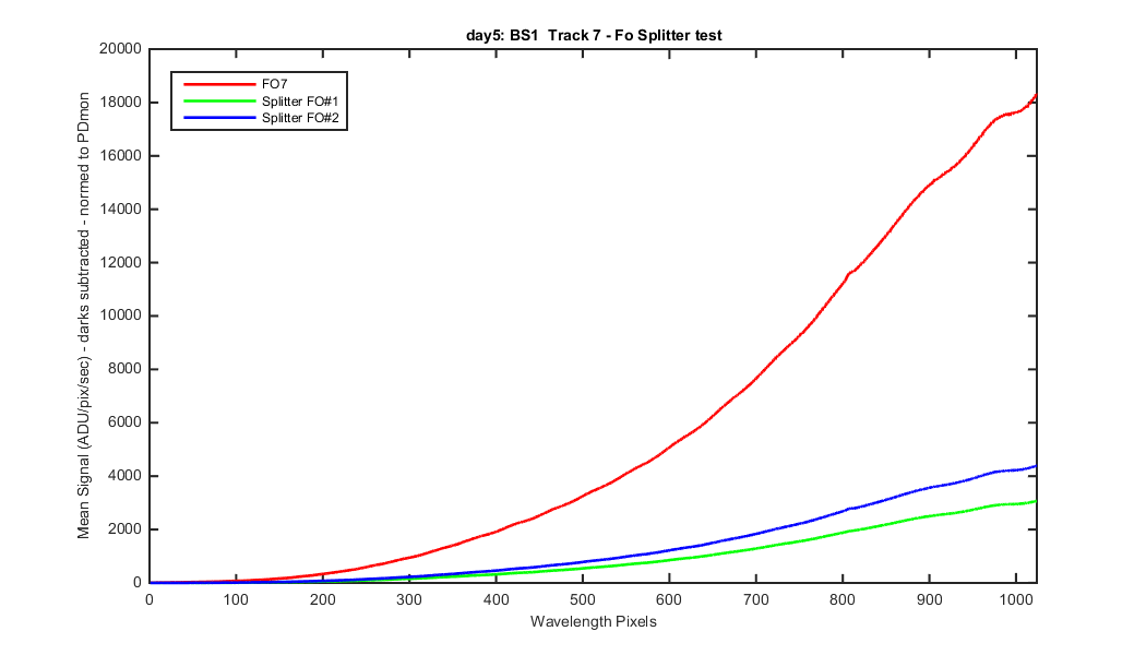
Figure 3
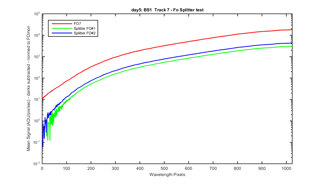
Figure 4
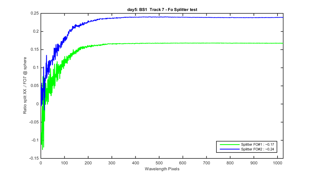
Figure 5