BS01cfg003 damage during shippment page
Below are the emails about the damage and a movie showing the damage
Intial email from Ken and Art
Hi Mark and Mike,
I am not sure what is supposed to move and what is not….but I don’t think these pieces are supposed to move….when we unpacked the spectrometer from the box we found the spectrometer tube was loose where it is connected to a block, which is connected to the camera, and the end cap on the tube is also loose as
this video shows….. (*.mov - 2 MB)
Then Mark, I was sort of expecting a shutter block and control….I guess how do we proceed with what we have? I can set up a falcon that we have here, connect it to the camera and the two lab jacks. One lab jack should be connected to the analog signals out from connector one and two on the side of the resonon block. The other is for the shutter control block which we can pretend like it is connected somewhere I guess….what do you think?
thanks
Ken
Mikes response
That looks really bad.
I made two modifications to that shipping box - adding the tube around the bundle,
and adding the 2x 2"-thick more-dense white foam pieces at either end. I left
~2"-thick softer black foam at the very ends of the box for cushion. So I'm wondering
if any of that contributed to the failure? The RS1 that arrived yesterday did have a
piece of clear plastic tubing around the bundle - Steph has photos of that on her ftp.
We did pay for $50k FedEx insurance on that shipment.
Kens email
There was no damage to the box, so I don’t think Fed ex would do much.
When Mark responds (I guess today is PT), we may want to ask Mike K what the inside of the spectrometer around that tube looks like.
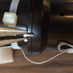
As it wasn’t right anyway, I took the first plate off of the back of the spectrometer (three screws…very small allen wrench). After those three screws are taken off, the back plate is just a press fit, with an o-ring, around the main big cylinder that says Resonon. This back plate is screwed onto another plate which has four screws (which you can see three of them) and the silver fiber tube is connected to this plate. That plate that the fiber tube is connected to “floats” inside the bigger tube….It doesn’t seem there is any positive connection that keeps the whole thing together.
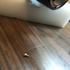
Note that when I took the first plate off, that screw shown in the second picture dropped out (never a good sign), but I cannot see where that screw goes in the parts that I can see.
I definitely think we need to bring Mike K into the picture, but I will wait for Marks opinion. I don’t think it was Mike F’s packing that was the problem….my wild guess is that there is nothing really positive holding that endcap on. The instrument was pressurized (there is a nice schraeder valve on the system) with dry nitrogen. In the air shipment, the external air pressure was low enough to blow that endcap off. But the main thing I see as weird is there does not appear to be a positive connection from the front block of the spectrometer to the back cap (say a set of rods, either internal or external running from front to back), so the system is sort of fragile….Perhaps we will have to construct an external cage to stiffen and make it more robust..or maybe that has to be part of the internal spectroradiometer design…..
Ken
Marks email
What the heck!
I don't know what to think about this.
We need to also worry about the CCD window If there was an internal pressurization of that magnitude.
Be careful if you power up the CCD. The CCD could be damaged by the cooler over heating If the vacuum capsule is compromised.
Kens email
how do you think I can check the vacuum? the main problem is there is no real way the whole thing (end cylinder) is kept together other than the press fit with the o-ring, as far as I can tell….
Unless you know how the spectrometer looks inside, we should probably bring Mike K into this, that OK with you?
Ken
Marks email
Resonon definitely needs in.
Perhaps the retainer screws were not long enough (too few threads) to keep the end cap and housing in place. I can't imagine the design relies on press fit considering the end cap apparently also holds the fiber bundle in place.
Mark
Ken's email to all
HI Mike and Casey,
We had a failure after shipping BS1 to Miami from Hawaii. When I opened the case (no external damage, everything looked good) and started to lift BS1 out of the case I noticed that the tube (that says resonon) flexed with respect to the block that is attached to the camera. Art and I then carefully lifted the spectrometer trying to hold as many parts in line as possible and placed it, supported, on a table. We noticed (
as shown in the video) that the cylinder was loose with the block attached to the camera, and also the end cap was loose (and as you can see basically loose enough to come off).
I also took the outside end cap, which fits around the fiber bundle (
picture shown below), off to see if something was broken..the screws holding this endcap were fixed solidly so that was not the problem. Interestingly there was a
loose screw that fell out when the endcap was completely removed. I can’t see anywhere that that screw might have come from…so it is either extra, or from much deeper in the system.
Obvious questions:
1) what do I do now?
2) Was there something that held that endcap in place? It seems like it is just a press fit around the outside of the cylinder, what am I missing?
3) any idea where the screw came from?
4) what does it look like, mechanically, inside that cylinder?
thanks
Ken
Mark email
Kens email
rigidly meaning what? if you look at this picture, the fiber bundle is rigidly attached to the silver piece. this is not rigidly attached (now) to the other end (the block attached to the camera). I have a feeling that I could remove the outside cylinder completely off of the system now, but of course would not think of doing that until I hear from Mike. It has to be that way, as it is the only way I could see that they could have put the system together in the first place.
Ken
Mark Email
In looking at the video, I see the silver bundle part moving relative to the outer cap and outer tube. I cannot see if the silver part is moving relative to the CCD camera/ inner spec assy.
Mark
Casey email
Hi Everyone,
That is a surprise to both Casey Dodge and myself. We ship instruments all over the world and never see screws vibrate out. Obviously. this of great concern.
Regarding the system you have: It looks like the two pieces of the lens barrel have separated. We should join them back together before shipping the unit back to us to prevent any damage to the system. To do this, unscrew the three screws that hold the endcap on. Then slide it and the outer shell off over the fibers. This will reveal where the problem is. All the screws should be symmetrical, so it should be easy to spot where the missing screw is from and where the loose joint is.
Moving forward: We can Locktite all of the screws in the system. We did not do this before due to outgassing concerns, but I don't see any other way. Is this acceptable? Of course, we can retro-fit any system you ship us with Locktite.
Please let us know what you find.
Casey S.
Kens email
HI,
You are right…before I read this, I was walking through my lab and thought I would just try to pull the outer cylinder off (it was loose already). The two pieces of the lens barrel had completely separated (all the screws came out). I think there are two problems, the first being locktite might have helped. The other problem though is the screws that are there, holding the barrel together have only 0.15” of thread, and they sit on a shoulder that is >0.1” (I measured 0.12”). It looks like there is only about 3 threads, at most holding it on.
In your drawings, what depth did you specify the holes to be drilled and threaded to be? Could we use longer screws?
I have some pictures on my phone that I will send when I get a cable.
thanks
Ken
Kens email
Pictures of the inside, and the screw length: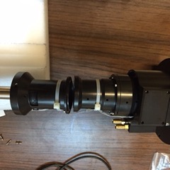
Marks email
I think that explains it.
Mark
Casey email
I agree. Hopefully this is the only instrument with the short screws. I will check the newly assembled Red that we have here. If you want to check the ones you have it would be a straightforward proceedure, if not you can send them back and we can do it here.
casey
Carols email
In the picture Ken sent, where is the PGP part? Is it possible the optics were damaged, or the camera?
Better to know this now than later. Carol
Kens email
I don’t believe anything was damaged. the screws that all fell out where external to the tube that contains the optics, and stayed external to the package. I think the main issue was that the screws, instead of being 1/4 inch were 5/32 or something around there. I checked one of the screws holding the next part of the system together and they were 1/4 “. I don’t have any cap head screws of the proper size (2-56 x 1/4”) so will have to order some.
I think on my end, I will just get some of the proper length screws and keep working with the system, unless people think I need to send it back to Resonon right now. What is the opinion on outgassing of locktite? Should I do that? Also, all the o-rings I have seen in the system seemed to have been assembled dry…is that normal (it isn’t what I was taught….but maybe there is an outgassing issue with o-ring grease?).
Finally, should I purge the system, after I put it together with dry nitrogen? My normal procedure would be to fill it with N2 to 5 PSI, then “deflate it” to atmospheric then repeat this process three or four times to exchange the air with N2…this sound right?
I would like to keep the system here, so we can get started on the software as soon as possible….
thanks
Ken
Carols email
I don’t know the locktite specs, but I would think the outgassing would vary as it sets up. Perhaps there are better materials. As for the o-rings and outgassing, there are some material selection choices for the o-rings themselves here if I recall correctly. And of course the grease.
Your plan sounds good to me. Carol