From pg.1 of "Temperature Sensitivity and Critical Tolerance Elements 11_03_17.pptx", in the Marklar drawing "Dual Spec Input Assy"
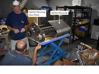
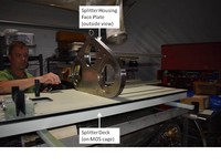
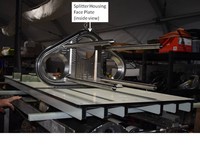
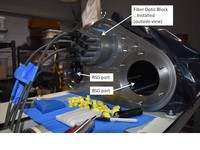
Photos 01,02,03*.jpg show the splitter housing and it's face plate installed on the splitter deck on the bottom MOS cage on MOBY265.
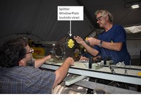
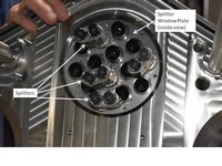
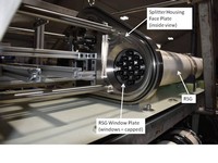
Photo 04 shows the splitter "Window Plate" installed on the splitter house = outside view (i.e. wet side), 05 shows the splitter window plate = inside view (i.e. dry side) w/ 4x splitters installed. In the drawing cross-section the window plate is @ x 4:5, w/ cross-hatching in the direction = '\', and is shown in end-view @ x = 7:8, y = A:B. The yellow caps in 04 cover the windows, which are @ x,y ~4.5,C = "Window Thor WG41050-A". The splitters in 05 are @ xaxis 5:8, yaxis C:D.
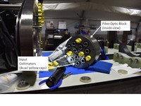
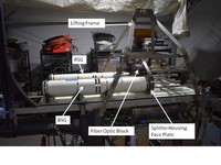
Photo 06 is the "Fiber optic Block" (or fiber plate, but it's a heavy block) = inside view. This gray block is @ drawing xaxis 1:3, w/ cross-hatching in the direction = '/'. In photo 06 there are yellow caps on the 4x collimators to be used for Es & Lu's, the other 10x collimators are not covered - in the drawing these collimators hold lenses L1 & L2 - they have a fine cross-hatch in the direction = '/' - and are sandwiched between the window plate and fiber block.
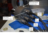
Photo 07 is fiber block outside view. The open threaded holes seen in the photo are at x,y 1,B and 1,C. The 4x gray tubes with black fiber hoses sticking out are not shown in the drawing, but would be off-drawing right-side - they screw into threaded holes @ drawing 1,B & 1,C. In the drawing @ 2.5,C is the fiber tip holder, which is inside the fiber block and held in place by the screwed-in smaller gray tubes.
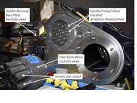
Photo 08 shows the 14x double O-ring pieces installed on the window plate - these are kinda seen in the drawing above and below the L1+L2 lens pair @ 4,C, with cross-hatching in the '\' direction (blank notches = O-ring grooves). These keep any water from a flooded fiber from flooding other ports.
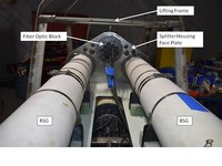
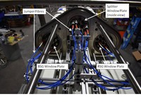
Photos 09,10 show the FO block attached to the window plate. Note the 2x big empty ports on the splitter housing end plate for the BS & RS.
Photos 11,12 show the BS & RS attached to the splitter housing end plate = outside view.
Photo 13 shows the RS (or BS?) installed = view inside splitter house.
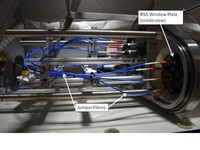
Photos 14,15 show the jumper fibers between the splitters and the BS & RS.
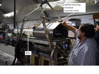
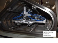
Photos 16,17 show the housing installed on the splitter end plate, outside & inside views.
01_SplitterHouse_A
02_SplitterHouseFacePlate_A
03_SplitterHouseFacePlate_A
04=SplitterWindowBlock_A
05=SplitterWindowBlock+Splitters_A
06_FOblock_A
07_FOblock_A
08_FOblock-installed_A
09_FOblock-installed_A

10_FOblock-installed_A
11_BS&RS-installed_A
12_BS&RS-installed_A
13_BS&RS-installed_A
14_JumperFibers_A
15_JumperFibers_A
16_SplitterHoused_A
17_SplitterHoused_A
_tn.jpg)
Fig.1=DualSpecInputAssy,Rev2_A(MF)
_tn.jpg)
Fig.1=DualSpecInputAssy,Rev2_B(MF)
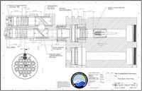
Fig1_DualSpecInputAssy,Rev2