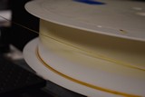
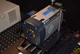
"Mike Kehoe fiber bending experiment": DAY 01 Mark bought the 2x filters shown in Mikes' Fig.2, and I started trying to figure out what to do with them last Thur/Friday. Monday I polished the ends of a 23 foot long piece of Polymicro 600 um fiber = end of the spool used in Dec-2016 M262 BS01 LuBot. Today/Tuesday I got the Andor CCD-16345 = was BS02 camera working and started collecting some scans.
The idea as I see it is to look at the images of
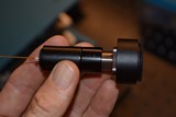
1. the end of the bare fiber
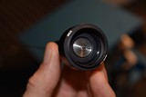
2. the output of the aspheric lens #1
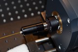
3. the output of the plano convex lens #2
with the fiber straightened and coiled up.
Today I collected some images of step 1 & 2. I was hoping you could look at these please. Step 1 bare fiber images don't look very good to me via SOLIS software, but maybe you can zoom in on the "tiny" fiber signal in the middle of the images? Step 2 lens #1 output was much more visible via SOLIS, but I'm not sure if just the very centre circle is the fiber tip and the rest if reflections off the silver threaded-barrel that hold the tip? I collected 3x pairs of sig & bac scans for each scan-set. And, I collected some dark scans to look for ambient light leaks.
Day2: After the telecon idears this morning, I tried fixing up some issues with the fiber-bending setup, and remade measurements for 1. bare FO 2. aspheric lens #1 which - to me - made much more sense than day01 data.
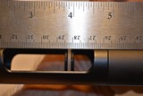
Day3 was Friday, GMT 15-SeP-2018, wherein, I reset the back focal length for the asPheric lens at the correct 12 mm - it was incorrectly @ 13 mm on day2, and re-scanned the coiled and un-coiled fiber Day2 SteP#2 data, then I setuP the lens #2 = Plano convex for SteP#3 = back focal length = 297.3 mm - which I thinketh I got nearly exactly = distance from front curved face of the aspheric lens #1 to back flat face of plano convex, and focal length = 300 mm - which came out at aboot 301.8 mm = distance from front curved face of the Plano convex to the camera window.
Day4, Whilst writing up results for Mike K. today I discovered notes I wrote down from the Thorlabs website r.e. the Plano-Convex lens, which said that the collimated light is incident on the curved surface - which I think is backwards from how I installed that lens. Perhaps this is why the step#3 images are not focused down! I'll try re-doing this early tomorrow before my 4pm tooth pull in Kailua...
Day4 part 2 email, I re-did the lens#2 setup and re-took step#2 scans, and also took some *day4* photos. There are also 2x *AutoCAD*.pdf spec sheets for the 2x lenses in the /doc/ dir. Maybe I will not talk much during tomorrow's telecon... My head hurts, MF
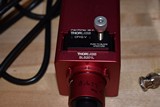
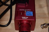
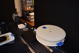
Day5 email, Today I mounted the Thorlabs tungsten source to a piece of plywood such that it can remain powered on and be moved from the long-FO=coiled location to the long-FO=un-coiled location. Today I took a set of data = day5, with the same setup as day4 - which was long FO + 2x lenses = "step3" w/ long FO = coiled - but I tried to see if the integrating sphere could be de-coupled from the input-end of the long FO then re-coupled without changing the image quality / intensity too much. This is a first-step to answer Ken's question during the Thursday telecon: can the long FO be coiled & un-coiled and give repeatable measurements? MF
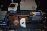
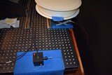
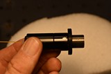
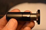
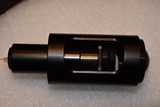
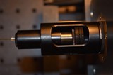
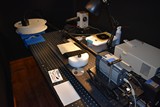
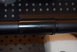
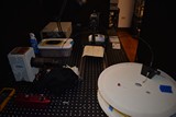
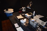
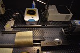
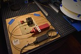
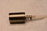
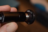
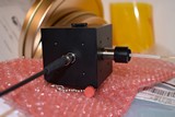
20180910_01=step0-fiber-setup
10-Sep-2018 19:54:57
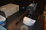
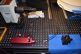
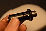
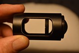
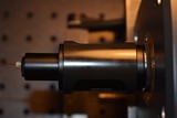
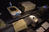
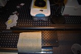
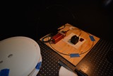
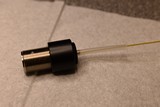
20180910_02=step0-fiber-setup
10-Sep-2018 19:55:45
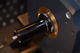
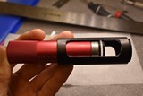
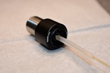
20180910_03=step0-fiber-setup
10-Sep-2018 19:56:18
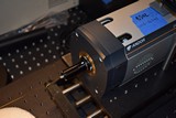
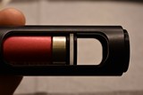
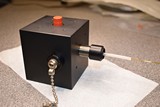
20180910_04=step0-fiber-setup
10-Sep-2018 19:57:04
20180910_05=step0-fiber-setup
10-Sep-2018 19:57:16
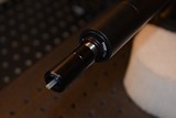
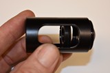
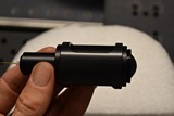
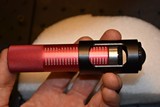
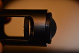
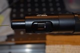
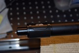
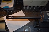
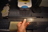
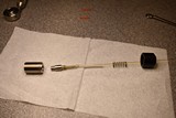
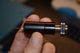
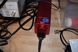
20180910_06=step0-fiber-input
10-Sep-2018 19:58:10
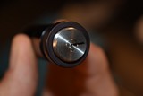
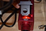
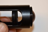
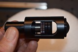
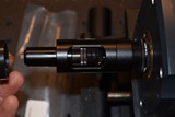
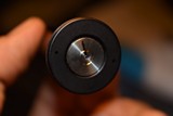
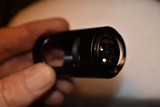
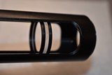
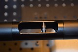
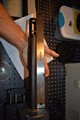
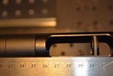
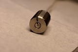
20180910_13=step0-fiber-output
10-Sep-2018 19:59:42
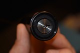
20180910_12=step0-fiber-output
10-Sep-2018 19:59:50
20180910_14=step0-fiber-output
10-Sep-2018 20:00:17
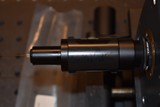
20180910_15=step0-fiber-output
10-Sep-2018 20:00:23
20180910_16=step0-fiber-output
10-Sep-2018 20:00:45
20180910_17=step0-fiber-output
10-Sep-2018 20:00:54
20180910_18=step0-fiber-output
10-Sep-2018 20:01:18
20180910_19=step0-fiber-output
10-Sep-2018 20:02:28
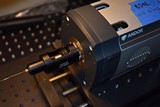
20180910_07=step0-fiber-input
10-Sep-2018 20:12:07
20180910_08=step0-fiber-input
10-Sep-2018 20:13:52