_bg.jpg)
_bg.jpg)
| Page num | Link | Description | Date |
|---|---|---|---|
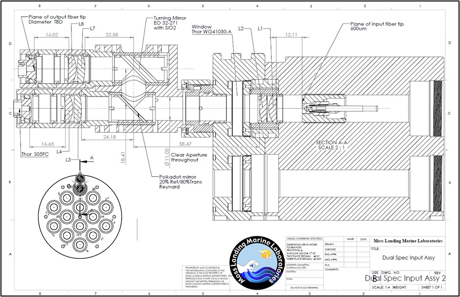
| 1.01 | Temperature Sensitivity and Critical Tolerance Elements 11_03_17 |
Temperature and Alignment Sensitivity, Dual Spec Input Ass’y for PDBS |
15 May 2018 |
| 1.02 | Splitter Labeling | Photo of PDBS with labeling of parts | 15 May 2018 |
| 1.03 | 20180517_MOBY265_pre-deploy_assembly | Mikes photo documentation of parts and assembly | 16 May 2018 |
| 1.04 | Mikes PDBS images | Mikes splitter photos of the guts of the PDBS | 22 May 2018 |
| Mikes colored and annotated versions of Marks drawings (see Page Num 1.03 for all the images) | ||
|---|---|---|
 |
_bg.jpg) |
_bg.jpg) |
| Page num | Person | Description/email/conversations about the docs and images above and general conversations that need capturing | Date |
|---|---|---|---|
| 100.01 | Mark on discussion of how temperature effects PDBS | You can kind of see in the cross section how the mirror is sandwiched between the two 45° holders and epoxied into a tube that is inserted into the splitter body. I don't think there is any chance the mirror epoxied parts (mirror, two 45° holders and the tube) move relative to one another. Movement could occur between the epoxied mirror tube assy and the splitter body. There are 6 set screws, 3 at top and 3 at bottom that are used to tilt the tube for alignment. The reflected path has an additional set of screws that adjust beam separation. All those screws are locked tight bit still they would be an area of concern. Tightening them too tight will break the mirror. I have started using Loctite that the Loctite company and NASA say does not outgass. The two prototype splitters that Carol is using do not have the Loctite since we want them to remain easily disassemblable. attached file being discussed is Temperature Sensitivity and Critical Tolerance Elements 11_03_17 from page number 1.01
|
5 May 2018 09:51:56 |
| 100.0101 | Mikes notes on Temperature Sensitivity and Critical Tolerance Elements 11_03_17 file | Hi Steph,
Note: the numbering of the BS/RS lenses might have gotten changed from fig.1 (and my note above) because the BS was originally on the
transmitted side of the PDBS and RS was originally on the reflected side
of the PDBS, but they got swapped somewhere in the modelling process. |
14 May 2018 7:27 PM |