Hi Mike,
We replaced the the Schrader valve on BS01, and realigned the unit. Ken had told us that he replaced the short screws in the middle joint with longer ones, and I took his word on this and did not check. I did replace the screws that hold the camera mount in place with slightly longer ones, and when I was tightening them as one of them felt a bit 'mushy'.
Regarding the packaging, I was a little confused as to the reason for all of the extra foam bits in the case but I repacked it the way it arrived in case someone had good reason for it! I am not sure why the cords are out of the power supply cutout- were the zip ties intact when you receive it? One of them had pink zip ties, the other one white if I remember right.
Thanks,
Casey
Hello Casey,
Thanks for the BS modification update. Do you have any data after the alignment? Stephanie has made a good habit of checking track alignment
changes before/after shipping events...
There was only one pink zip tie on that shipping case, but it was zipped
down tight.
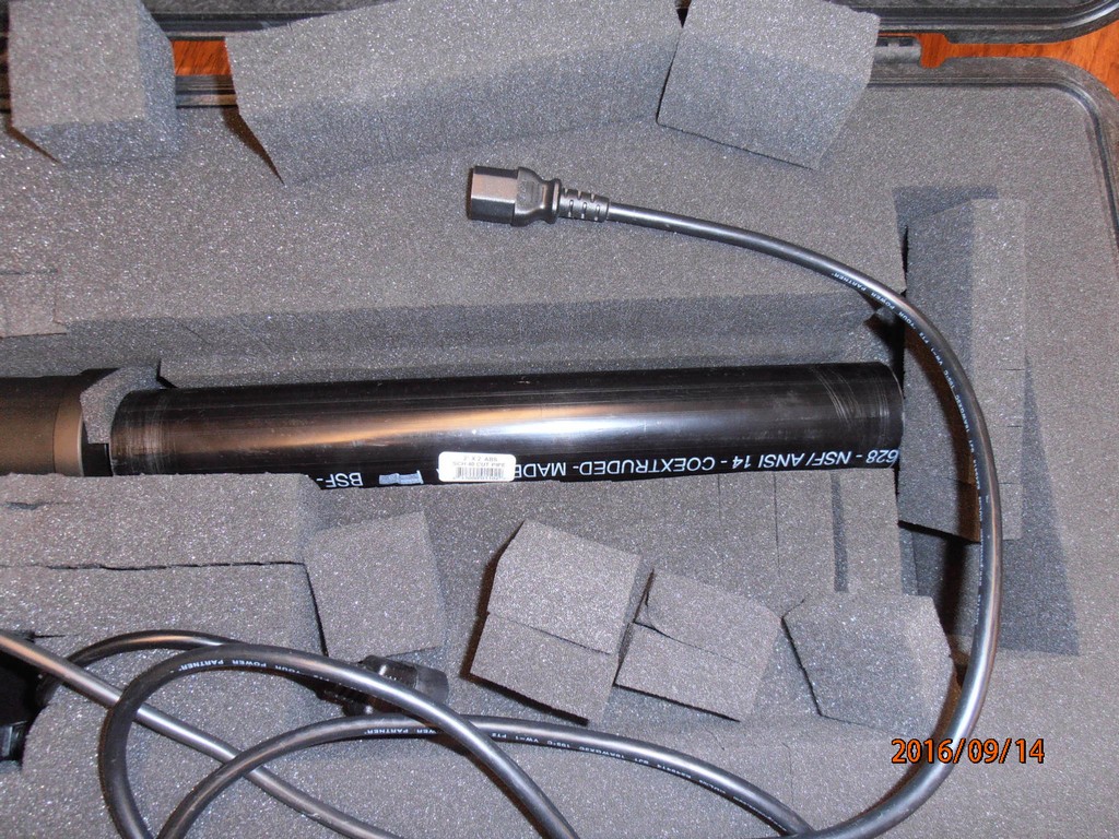
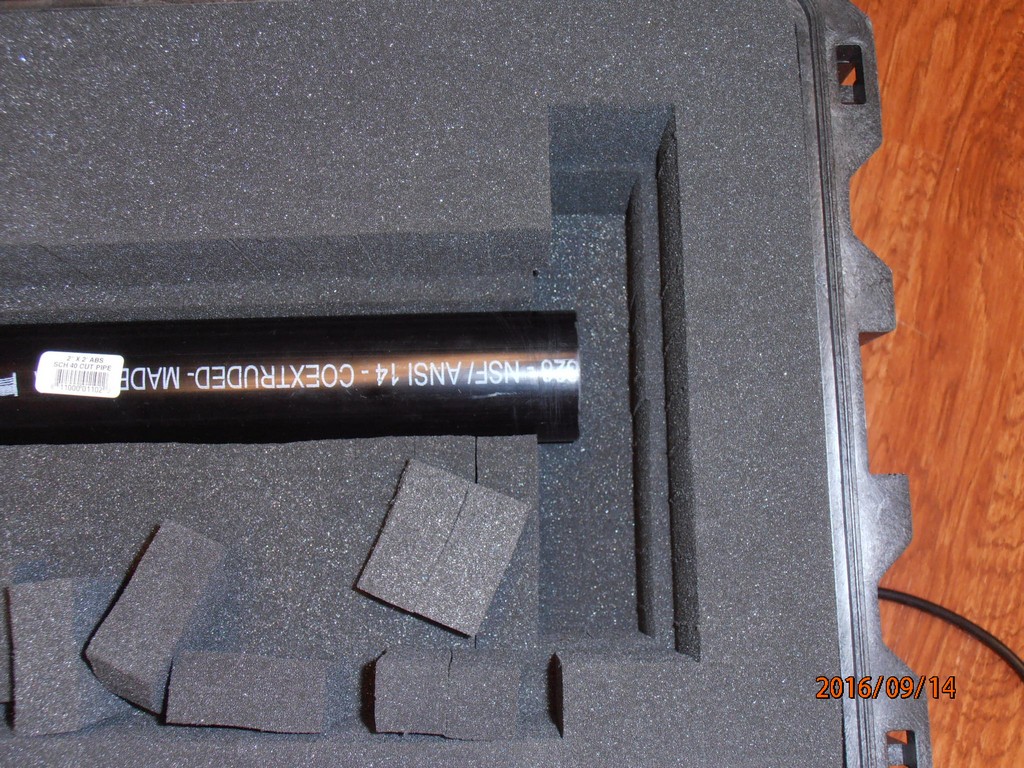
At Mark's suggestion, before shipping to Miami, I had added two pieces
of more-dense white foam at the ends of the case - the one at the camera
end is still in place, but the one at the fiber-tip end is missing, so there is
an empty space in the black foam at the fiber-tip end which might have
allowed movement of the PVC tube around the fibers, which in-turn might
have allowed the instrument to move end-to-end (?).
<attached 2016-09-14_04, 05=BS01cfg00x.JPG>
Cheers, MF
Hi StepH,
Guess what?
We have more BS data!
I had the thought that this might be a better BS to deploy with MOBY262 - on account of we have some history with this BS -
so, well, here we go again:
/ftp1/Mike/HI-2016-09/BS01data/day01/ has 12x bac,sig pairs,
3 repeats each at 4x Andor TEC temps: off, -20, -40, -80 degC,
plus 1x log sheet scan, plus 1x ad*.dat file.
'Njoy, MF
Hi Casey, Stephanie & I were looking at some fresh data from the BS01cfg005, where she re-defined the track boundary pixels, and I was wondering... when you said you "realigned the unit", could this possibly shift the track positions on the detector? And, just to be clear, was this "realignment" different than "refocusing"? Here, I am thinking about the refocusing that occurred back in the day, between the fiber-bundle inputs and the slit... Thanks / Happy Friday, MF
From Casey
The realignment covered almost every adjust, and yes the track positions undoubtedly moved.
Hi Steph,
I took the BS01 outside after the sun went behind the Kilo Moana,
to collect some bare FO Fraunhofer scans today, so,
there are 5x bac/sig .fits file pairs + 1 log sheet + 1 ad file on your FTP.
The b/s scan # 01 had white caps on the FO tips, pointed @ gray plaque,
# 2,3,4 had trk # 1, 7, 14 tips uncovered pointing at the gray plaque
with all other FO tips capped & covered via black cloth, and
# 05 had all FO tips capped & covered so this sig should ~= dark scan.
That's aboot it for tonight! MF
Hi Steph,
There are some more data to challenge your processing skills at
/ftp1/Mike/HI-2016-09/BS01data/day03 !
There are 23x sig&bac pairs of .fits files.
Plus there are 2x log sheet scans = BS01cfg005_log_03, 04.jpg
plus 1x PD monitor file = pd2016101801.txt,
plus 1x AD aux data via the LabJack = ad2016101801.dat.
All BS scans were via trk#7 @ 1 sec exposure @ 500 nm.
Scan #1 should not be saturated. Scan #2 to #23 were taken
at increasing laser power settings. Laser power was increased
by decreasing the pulse delay usec (micro seconds)- noted on the
log sheet. This increased the laser's internal 355 nm PD mon
mJ (milli Joules) energy reading, also noted on the log sheet.
The PD mon file has sphere level Amps during the BS scans,
so this should be a reference for the "power" of the saturated
peak. After each BS scan I placed our Gentec laser power detector
at the Ekspla output port - between the laser & the fiber-optic coupler -
so during the power meter reading the sphere PD mon level should be ~zero.
On the log sheet I noted the range of laser power meter readings in
mW (milli Watts). There is also a "zero" mW reading which is via the
power detector out of the laser beam. I will continue trying to figure out
how to "zero" this meter! I am hoping that the range of power meter mW
will make sense when compared with the range of PD monitor Amps
collected just-before the mW readings!
I have absolutely no idea what the BS sig data look like! The Solis
acquisition software is also in need of figuring out how to be
zoomed into the CCD image data, by I...
This is probably a very rough first try. I started Friday afternoon, hoping
to get some data for Ken's poster, but I got stuck aligning the laser with
the FO coupler and I got confused by the non-zero mW readings from
the Gentec laser power meter...
GOOD LUCK WITH THIS ONE! MF
Hi Steph,
I just ran the BS01 on the DC-DC power supply that Mark built to test
the RS01 in the HI-bay with post-MOBY260. Tonight I ran the BS01 +
DC-DC pwr sup via 1 MOBY 12V truck battery in Pier 35, room 124.
The camera was cooled at -60 degC. I collected background and
dark scans (where "dark" is a SOLIS "signal" scan with the lights out,
and the SOLIS "background" does not fire the shutter...)
at 0.1 to 60 sec exposure time to look for any possible sine-wave noise.
The data are at /ftp1/Mike/HI-2016-09/, with 1 log sheet scan +
1 aux .dat file, + 3x photos of the setup, + 8x b,d*.fits scan files.
If there is any sign of noise in the darks I can re-do this experiment
using the Andor AC-DC power supply as a reference...
Happy Holiday Tomorrow! MF
Hi STeph,
I repeated the day04 dark data scans via BS01cfg005 @ camera pre-amp gain = 2x.
The .fits files are on their way to /ftp1/Mike/HI-2016-09/BS01data/day05,
plus one aux .dat file, plus one log sheet scan .jpg file.
Easy Peasy right?
Thank you very much, MF