I ran the BS01cfg02 tonight, with the Ekspla(cfg09).
The BS01 returned from Resonon with a different Andor camera than it shipped out with -
I'll look for this new camera's spec/docs tomorrow.
Tonight was only a test to get some quick data for Ken's NOAA/JPSS talk.
I did not collect no stink'n Aux temp/humid data.
I'll try to setup the Aux data acquisition tomorrow,
and we'll see what more data Ken might like to have ASAP.
Tonight I scanned:
450 nm w/ all 14 FOs, then only FO #7, the only FOs #4,7,10,
350 nm w/ only FOs #4,7,10,
680 nm w/ only FOs #4,7,10.
Luck, MF
There are some new data for you at the nas ftp. I changed the physical setup tonight, but only manipulated one parameter in software. I did not get to setup the Aux data acquisition.
There was only FO #7 coupled to the integrating sphere, without the FC ferrule coupler, and using a thin one-hole "jig" at the sphere's exit port - seen in photos 2015-07-01-01 to 05.jpg.
I de-coupled the Ekspla FO from the entrance port of the sphere - photos #06 to 08. This was to keep the laser power up, and stable, but decrease the level at the sphere exit port, to keep the camera's exposure time highish.
I also monitored the sphere's power level via a PhotoDiode Monitor (PD Mon on the logsheet, in current units of nA) - photos 09,10,11 show the PD Monitor on the sphere, the Thermal Electric Controller (TEC), and the Keithley DVM (in "I" = current mode).
In software I only changed the "Shutter open & close delay" time (msec). I scanned background (b* files), then signal (s* files), then Stopped the laser to get a dark scan (d* files). This repeated for shutter delays at 10,15,20,25,30,35 msec (open & close delays kept equal).
I did some rudimentary data-processing in MATLAB after each dark scan, - while the laser was re-started and stabilizing - and it looks to me like the shoulder at the high-pixel-side of the peak went away at longer shutter delay times. I think the darks looked same as the backgrounds (at least near the laser peak).
Maybe tomorrow we'll try leaving shutter delay alone and change the integration time - so that the difference gets larger...
MF
Mark reminded me of a more interesting idea for data tonight: a sun scan ! There are photos of the setup, and of the sky conditions at your nas ftp, as well as a one-page log sheet. There were 8 signals + 8 backgrounds acquired. I did not get the Aux data running. Track #7 FO was coupled to a MOBY Ed head (post-MOBY257 EdBot = head # Ed42, via a long ROV FO between the tent & the laser van), all other track/FOs were capped. The first 4 scans had Ed pointing straight up, sitting next to the tent. Then I thought it might be nice not to "see" the tent, so the next 4 had the Ed mounted on a tripod, pointed towards the (lower) sun.
Luck, MF
There are some more BS01 data for you at the ftp, from day04 & 05. Day05 was essentially a repeat of 04, except that I cleaned out a bad FC connector on the splitter for 05. There was epoxy at the bottom of the "WEAKER" splitter FO - I tried to take photos before I chipped it out. The epoxy did not allow the WEAK FO to seat on day04, so I think those scans are bogus - hence the day05 repeat.
I used the Oriel incandescent source with the 12" Spectralon sphere. I ran the TEC photodiode monitor and hand-logged it's current output. I bought some new HACA FC-to-bulkhead connectors and made a jig for the 12" sphere - see photos. First I connected BS01 FO#7 to the jig/sphere - collected 5x sig/bac scans. On the logsheet are photodiode monitor levels, ~19 uAmps, which we may need to normalize the BS01 data to. Then I connected the single end of the splitter to the jig/sphere, and in-turn each of the split FO ends to BS01 FO#7 using the new FC-to-FC connector ADAFC1 - see photo of this conn. I do not know what the loss off this connector is - I suppose we're about to find out ! One of the two split FO ends is labeled "WEAKER" the other is not labeled. At the very end I collected 3x sets of sig/bac after the lamp was turned off * these signals are d* files, or darks.
I think from this set we can do a first check of the relative throughput of the two splitter ends. I think they will be less than ~50%, as the splitter spec sheet says, because of losses at the FC-to-FC connector.
I thought the Oriel incandescent would be more stable. Maybe the pd monitor levels will help correct for it's instability. I can make a HACA jig for the NIST OL455 - it is 1/2 done - and we can repeat this with that source if needs be. The OL455 also has a pd monitor, but it has no TEC / temperature control.
Luck ! MF
I re-ran the day 05 splitter kine tonight. This is log sheet #1 of 2 for 29-Jul / page #6 overall. I only scanned the 2 bare splitter fibers - with ~50kADU @ splitter FO#2, then FO#1 at the same exposure & gain - to see if we can repeat the FO#2 / FO#1 ratio from day05. There are again photodiode micro-amp readings to use for normalization. These were sig & bac files, 5 each for the 2x FOs, for a total of 10 files, plus 1 pair of dark & bac @ the end.
The second setup was per Ken's suggestion. I got the Es head from MOBY257, and the EdBot fiber, and used the Oriel incandescent lamp to illuminate Es. This is log sheet #2 of 2 / pg.7. The Es head & EdBot fibers' FO connectors were cleaned. The Es-to-FO connection got coupling gel. The Es head collector was also cleaned. I used the Es head's alignment jig for FEL cals to mate to the Oriel lamp. There are 6x photos of this setup. The splitter input FO went into the end of the EdBot FO from the Es head. Either splitter output FO#2 or FO#1 went into the BS01 FO#7. I rotated the Es head 3 times for each splitter output FO connection, such that the Es head orientations were 1 = straight "up", 2 = 90 degree rotate, 3 = 180 deg rotate, 4 = 270 deg rotate. There were no photodiode monitor levels for normalization. This was a quick setup. I imagine that the mating between Es & lamp was not perfect for each rotated state of the Es head. I don't know how much the lamp varied during these measurements, so I don't expect the ratios to be flat & equal to one. Each of the 4x rotations for the 2x FOs had a sig & bac file acquired, for a total of 16 .fits files.
Cheers, MF
There are 11 photos and 1 log sheet (pg.8) for day 07 = 30Jul2015 GMT, which was: MOBY257 Es head #Es40, via EdBot FO #3005, and splitter SN: CERL15050101, with MOBY Es & FO connected to splitter input FO, then 2x splitter output FOs connected to 2x BS01 input FOs: split FO#1 to BS01 FO#5, split FO#2 to BS01 FO#10. Measured were 10 rotation angles of the Es head @ 0:10:90 degrees - 0 deg was Es pointing directly at the light source, 90 deg was Es seeing the light source just grazing across the cosine bezel edge.
Each angle had 2x .FITS files collected, sig & bac, for a total of 20x files.
Tonight I did not try changing the bend in the splitter fibers - maybe tomorrow...
MF
And, I have another round of data from day08 - I repeated the 0-to-90 degree Es rotation of day07, butt with a longer MOBY FO cable between Es & the splitter. I was reading that the mode order is a function of fiber length, so it might be interesting to compare a short fiber = day7 via a ~3.75 m length MOBY EdBot FO versus day8 with a ~12.1 m length MOBY LuTop FO - both coupled to a MOBY Es head at one end, and coupled to the input of the splitter at the other end. I think the data processing for day8 would be ditto that of day7, ...including my above request for saddle overplots along the spectral dimension. There are 20x .FITS files and 1 log sheet .jpg at the ftp site for you!
Be thee here fore-warned - I have dug out our polarizer filters, and I have read up on the polarization tests we did for MOS, and I have read aboot Stan Hooker's polarization tests during SIRREX-7, and how polarization was characterized for POLDER, so I am planning
to collect some polarization data next week!
Thank you! MF
Hello,
On Monday I got the BS01 auxiliary data cabling / acquisition running, and
on Tuesday I re-ran the Day8 setup with these changes:
A.) increased exposure time,
B.) changed exposure time for different Es rotation angles to keep full ADU levels,
C.) changed fiber / track input at BS01 fiber bundle.
Attached here are my notes / figures until Steph gets back: <Day09_Results(MF).pdf>
I think the next setup will be using the laser source, and I heard Mike K's good idea
of fein-rotations at 0 to 12 deg.
Aloha, MF
Hi Steph,
I am in the process of FTPing to you the Day09 data for BS01 testing.
Yesterday I sent a PDF with results of my attempt at data processing.
There are 7x new photos: 2015-08-05*.jpg,
there are 4x new data log sheets: *log_10...13.jpg,
plus the writeup: Day09_Results(MF).pdf,
and there will be 80x data files: s,b20150805*.fits.
One thing I messed up: I did not save a b (background) file for #10 i.e. b2015080510.fits, so I made one by copying from b2015050809.fits,
which was at the same exposure time...
Once this is pau I'll be moving on to making day10 data ... after lunch !
Thank You, MF
I almost forgot...
I got the aux data stream for BS01 running again for day09.
I just FTPed the file to the day09 folder = aux2015080501.txt
I made it look like the files for HI-2015-01
( see aux_descrip.txt ) but I added a 7th channel
to log a thermistor at the splitter (Mark's request)
(see day09 photo 2015-08-05-03=aux-splitter-therm.JPG).
This Thermistor is a Cantherm CWF-4B-103G3380,
(which we used with the FISH for some kine external temperature),
for which I converted Ohms to degrees in MATLAB via >> t5=mythermcnv(o5,'\wrk\thermist\thrm_Cantherm.dat');
for which you'll want the 3rd order polynomial coefficients
in the attached thrm_Cantherm.dat.
FYI: I'm also attaching the R-vs-T doc for this thermistor:
Cantherm_RT.txt
Good Luck ! MF
Hi Steph,
Yesterday I started the experiment of a laser source input,
to a rotating Es collector, to long MOBY fiber, to splitter, to BS01.
I used split FO#1 to BS FO#3 / split FO#2 to BS FO#12, like day9 end.
There are 3x log sheets, for 3x wavelengths = 350, 375, 400 nm,
plus 10x setup photos, with 10x sig&bac for each 0:10:90 deg rotation
for each wavelength = a grand total of 60x FITS files.
Oh yah, there is also an aux2015081301.txt file.
On the log sheets are noted the internal laser PhotoDiode reading (Euv),
and the reading for the TEC-PD on the sphere - I don't think you
should worry about trying to normalize Andor data to these.
These first 3x near-UV wavelengths went very slowly because of
the low laser power and hence long exposure times, but I expect to
roll through more waves tonight - hopefully all remaining waves...
Next on the list is a bare fiber, rotating through its' ± 12 deg
acceptance angle, with laser input...
See YOu, MF
Hi Steph,
Day11 data are at your ftp site. 80 fits files + 1 aux file + 4x log sheets = page 17-to-20.
These would be laser waves 425,450,500,600 nm.
I found a BCJ email from 07-Aug-2015 suggesting "We only need a couple of waves past pixel 300
but if the scanning could be done more finely below pxl 300
we would map out the splitter ratio there." So maybe we'll want some more waves below pix 300...
MF
Hi Steph,
R.E. Your fig.10 from pg.11.01 = Fo Splitter sim,
(attached: plt_fo_splitter_mobyheads_day1011_t312__10.png)
1.) I'm beginning to think that rotation angle of Es collector is not an issue.
1.a) To me the saddle shape is an indicator of fiber mode behaviour (?)
2.) I'm beginning to think the track ratio is a function of track responses.
2.1) Q: Why does the track ratio not repeat for broadband vs monochrome source?
2.1.a) There were different exposure times / ADU levels for broad vs mono.
2.1.b) Different sources= ~point source / incandescent vs diffuse sphere / laser.
2.1.c) Stray light - SF thinks this is small except for 2nd order.
etc.
I will repeat the 7x laser wavelengths tonight,
to check repeatability of the track ratios,
but only at a zero-degree Es rotation,
probably filling in some additional wavelengths.
Steph reminded me to add the Mike Kehoe IR artifact waves at "715-720 nm and 920 nm and 955 nm".
I will vary the exposure time, and/or the laser power
- probably only at one wavelength -
to see if the track ratio changes with ADU level (i.e. linearity).
R.E. the bare FO ± 12 degree rotation:
I don't think this will work with an integrating sphere source,
because the FO will be viewing different surfaces of the sphere
as it rotates. I think this requires a ~point source. Thoughts?
Terrence is assembling the next MOBY and soon I will need
to move to MOS/MOBY cals, so my time for the BS01 will be
much reduced.
A.) I know the polarization check is on tap. I think
this should be somewhat straightforeward (ha).
B.) I have some bandpass filters/mirror that Mark bought from
Thorlabs/Edmond, plus SMA & FC collimators from the FISH,
but I have no clear plan r.e. how to go about testing their effects.
Aloha, MF
Hi Steph,
Day12 data are ftping now...
For Day12, I did not change the collector nor FO coupling from Day11.
Es viewed the Ekspla integrating sphere. Es was at zero deg rotation
to said sphere, and its' rotation was not changed. I re-ran the day10,11
laser wavelengths, and filled in some inbetween waves. I reckon we
should see if the day12 track ratios overplot with day10,11...
I also did a short check at 400nm of ~linearity = varied only exposure time
while keeping same source level to have a range of ADU signals to
check for any affect on track ratio. This is a cheap combination check -
there could be a non-linearity in exposure time, and/or there could be
a non-linearity in count level... I also ran some near-IR waves for
Mike Kehoe. I saw no sign of signal at 30 sec exposure time. This might
be better re-run with a bare FO and/or a radiance head, because the
Es diffuser in front of the sphere is already a somewhat insensitive
sensor...
Luck, MF
Hi Steph,
Day13 data are heading your way.
Only 1 log sheet scan = pg.23,
plus 1 aux file = aux2015081901.txt.
The fits 2 pairs - sig&bac - of .fits files are
Constant Wavelength, CW, lasers @ 543.5 & 632.8 nm.
The rest of the .fits files are via the polarizer, which is
a filter on a rotation stage, illuminated by the Oriel
incandescent source via the Spectralon sphere.
They were all at the same 30 sec exposure time, so I only
took a bac scan every 5th file. I really needed to to scan
at 60 sec or more but I was running late, and I'm sure this
will be repeated... The polarizer was rotated from zero to
90 deg at 10 deg intervals. The photodiode monitor on the
sphere had micro-Amps logged on the log sheet - hopefully
we don't need to normalize to these...
I'm just now noticing that 1/2 of the .fits files are 4 MB size...
I took some photos. The first 5 are of the CW lasers.
The first 4 of the polarizer photos were to document how
I aligned the filter in the rotator.
I have some docs I'll gather for the polarizer.
I have the doc of the SIRREX7 polarizer test,
which has a processing "parameter" which I think
we should compute. I'll get those together & send them next.
Thanks, MF
Here's the pages from the Melles catalog for our polarizer.
<attached= MellesGriot-DichroicSheetPolarizer.pdf>
Hi Steph,
Here are the pages from SIRREX7, chapt. 7.3, r.e. polarization
<attached= SIRREX7-Polarization.pdf>
I'd like to play with the "polarization parameter, P"
from section 7.3.3 and compare with their Table 11 results...
MF
Hi Steph,
Here is a graph with what one would expect to see (of course noise free). Notice, if you want, that the cosine is squared, due to Malus’s Law. Because of the trig identity cos(u)^2=(1+cos(2u))/2 you will also see this written as a function of cos(2*angle)….same thing. In fact when both MODIS and VIIRS polarization sensitivity were being measured, the clue that something was wrong was that they ended up with factors proportional to cos(4*angle) and not cos(2*angle). In general, you could take the raw data and do a fourier analysis of it, and the polarization sensitivity should show up as a cos(2* angle) component...
Ken
Hi Ken,
The polarizer is a Melles Griot 03-fpg-007 -
I attach here the "specs" from Melles <attached= MellesGriot-DichroicSheetPolarizer.pdf>
There are 2 "engravings on the outside edge" of the filter. I aligned the one near the Melles part# engraving with zero degrees on the rotator. The rotator ended up aligned to the Lu head at 90 deg - i.e. zero deg on the rotator was
toward & along the axis of the fiber connection to the Lu head.
I took some photos of this setup (see Steph's "Photos" webpage,
Date: 19-Aug-2015). I'll have a look today at the
min/max extinction of reflectance off Snug harbour water
relative to the engravings / rotator / Lu head.
Rodger the depolarizer. I'll get some help from Mark to
place it in front of the Lu collector head's mirror...
MF
Hi Steph,
On Friday I ran the BS01+splitter+shortFO+Lu via sphere+incandescent
through 2x polarizers. The idea was to check the polarization ability
of the optics to extinguish all signal when the optical axes were crossed.
The Melles Griot specs say the polarizers are good for 350-650 nm range,
so one might expect their ability to polarize light past 650 nm to decrease.
I'd been wanting to make this measurement because Bob Barnes told the
story that some NASA peeps had NOT done it, but I did not really understand
why one should do it...
There was really only 2 net-signals measured, with the 2 optical axes
parallel and with the axes crossed. I had to increase the exposure time
when they were crossed. The interesting thing I saw was Mike Kehoe's
IR artifact pop out with the polarizers crossed!
There is aboot to be ftp data for you = 1 log sheet, 6 photos, and
4 fits s/b pairs, plus one dark scan at the end with the lamp off.
I'm curious how the dark compares to the previous background,
because even though I try to baffle out all room light I have
2 laptops running and it is a small room...
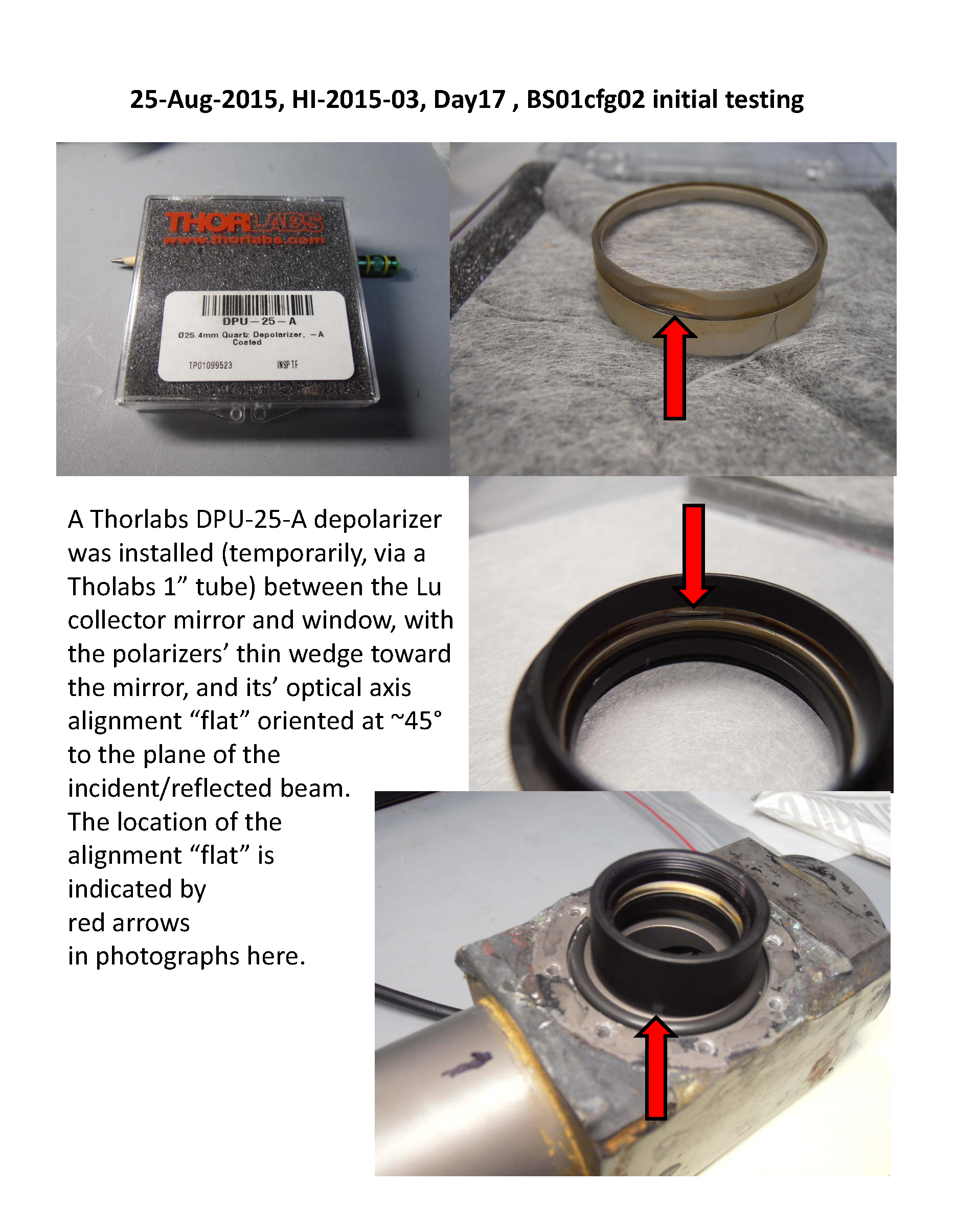
On Monday I plan to open the Lu head and put the depolarizer
behind the Lu window, then re-scan the single polarizer...
Thanks, MF
Hi Steph,
There are day17 depolarizer data coming your way. There are 10x sig/bac .fits pairs + one dark at the end.
There is one log sheet scan = pg.27, + 2x Thorlabs*.pdf docs for the depolarizer.
There are 8 photos. I tried to document the orientation of the
depolarizer - it has a flat edge on the filter to mark it's optical axis
(see Thorlabs_DPU-25-A-AutoCADPDF.pdf) which I tried to orient
at 45 deg to the plane of the beam to/from the mirror, for the
flat face of the depolarizer facing the mirror (as per Ken's email suggestion).
MF

HI Steph,
See if the attached document makes sense on how to use the fitted parameters (M12 and M13) for predicting the change in the MOBY measurement of Lu….then the correction would invert this….
ken
Hi Steph,
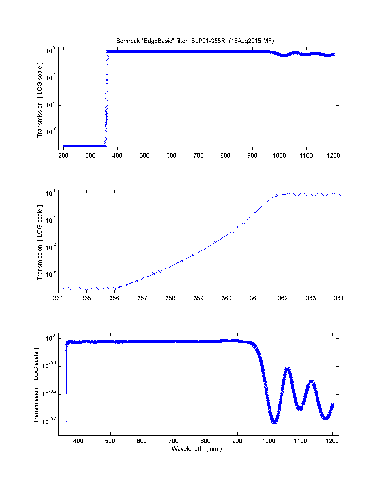
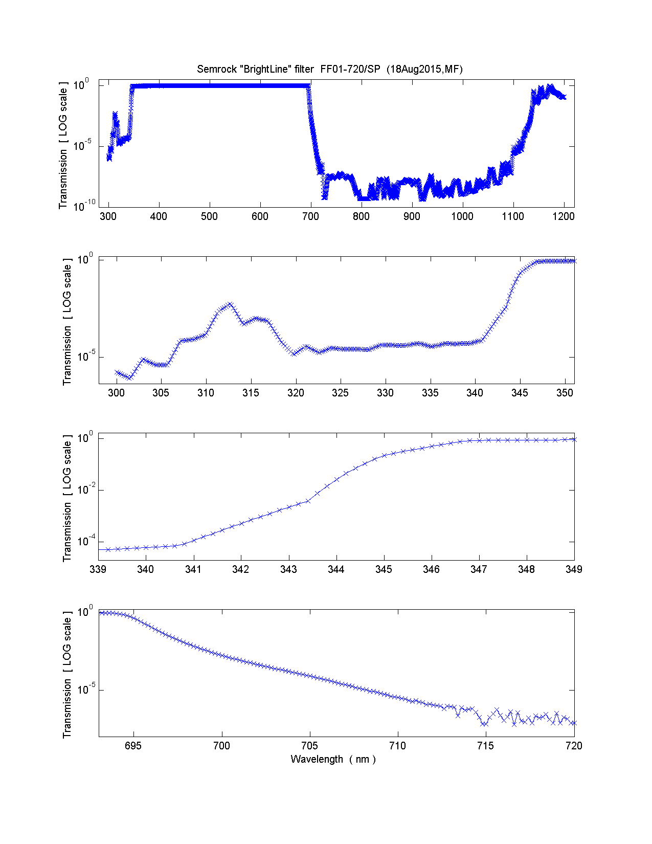
I took a few scans tonight = Day18. We are moving on to testing the long-pass & short-pass filters that Carol found-&-bought from Semrock. I think I forgot to
ftp this, so attached are some Semrock docs
BLP01-355R_Spectrum.txt, FF01-720_SP_Spectrum.txt
BLP01-355R-25_SemrockFilterDetails.pdf
FF01-720_SP-25_SemrockFilterDetails.pdf
Semrock_filter_documents_aug2015.pdf
and two plots I made from the .txt spectra
semrock_BLP01-355R.png, semrock_FF01-720_SP.png
The filters were mounted in Thorlabs 1 in dia tubes, then the two tubes were mounted together, then a Thorlabs collimator F220FC-A was mounted at the input & output ends. Docs for the collimators & the anti-reflective coating I did ftp to the doc dir. There are photos of the filters and their mounts.
The filters+collimators went between the splitter FO#1 and the BS01 track#16 FO. The splitter FO#2 was not filtered & was left connected to BS01 trk#3. The Lu head
and short FO connection was left unchanged from Day17, but I removed the depolarizer from the Lu head.
I thought I'd see if the filters removed the IR ghost which we saw via the crossed polarizers - they did - this was the first few three fits scans.
Then I tried to see if the filters removed any 2nd order signal from the UV lines from a HgA wavecal lamp. This idea came from the attached doc
I think I forgot to ftp this too... This did not happen. Something in Lu head - maybe the mirror - and/or the fiber already removed the UV lines - just like I noted in the Hg-Ar...txt doc for MOBY... The HgA scans in fits files *.04 were saturated, but the *.05 were not. Maybe the 05 will be good for wave cal training!
Next / tomorrow I reckon will be laser line scans near the filters cut-on/off wavelengths...
Luck, MF
FEL lamp polarized output - document
Hi Steph,
There are some new BS data for you! I am combining day19/Friday with day20/Monday,
because they are all Ekspla laser data through the
combined LongPass + ShortPass Semrock filters,
which are on Trk#12, with no filters on Trk#3 for reference.
The wavelengths scanned were a bit mixed up - sorry.
On Friday there was no trk#12 sig below 360 nm.
Monday I fein-scanned 357 & 362 nm = around the tiny 360 nm sig,
then I scanned 410 nm to off-the-array 700 nm, on Monday.
I also tried to collect some data for your comparison of SL vs MOS.
At 460 nm I got 2bac / 5sig / 2bac. The file numbering might be
a hassle for you - let me know if you think of a better way to
number this kind of scan set...
There are 2x log sheets + 2x aux files + no new photos.
Good Luck!
MF
P.S. Terry is making progress assembling MOBY259
(I think we're waiting on Mark who's working on the new controller)
so this BS should be nearing a pause someday soon...
Hi Steph,
for the plot of SL vs MOS I collected some more 460 nm scans tonight, all at 2 sec exposure and 4x preamp gain, but at different combinations of Horizontal readout rates and Vertical shift speeds. There are a bunch of dark scans at the end of it all. There is one log sheet, one aux file.
Luck! MF
HI Mike (and all),